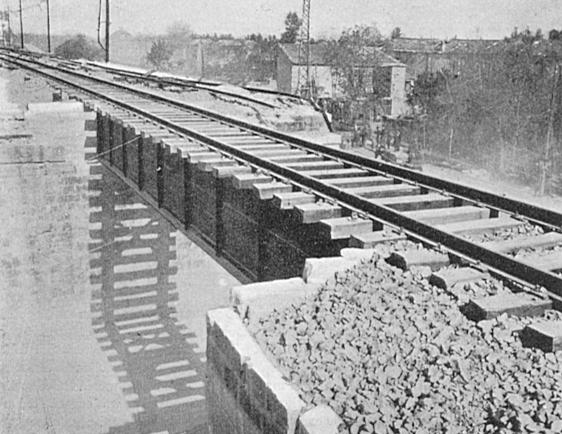
Figure 19. - Line 89. Bridge 2 at Km 190,3, North of Aversa. Repair, using a 40' plate girder from Steelworks in Naples, was carried out by 150 Rly. Constr. Coy., R.E., under Job Nº. 89/6, from 15 March 1944 to 11 April 1944.
[Railway reconstruction Italy 1943-1946 published by Royal Engineers, 1946]
| Prev | Contents | Next |
Chapter II
DESCRIPTIVE ACCOUNT OF RAILWAY CONSTRUCTION ACTIVITIES
Section III.
Railway Construction considered in relation to the ultimate Railway system
3. - Line 89. Rome - Naples Direttissima. Rome-Formia-Villa Literno-Aversa-Naples.
This line is of comparatively recent construction, having been built during the Fascist regime in order to provide a more expeditious connection between Rome and Naples than was available over routes then existing. Curves and gradients are very easy and everything on the line is designed to facilitate high speed running. The line was double track throughout, operating by electric traction and fitted with colour light signalling and electric point operation.
Starting from Naples, the line strikes inland travelling first North, the North West and finally due West across the plains to the North of the city. On reaching the junction station of Villa Literno it turns North West again in the direction of Rome. Crossing the Plains of the Volturno River, it then tunnels under Mount Massico and comes out into the plains of the Garigliano River, crossing the Garigliano River, the line turns to the coast, skirting the shoulder of Mount Aurunci and runs West through the coastal towns of Minturno and Formia. At Formia, the line turns North West and tunnels through a spur in Mount Aurunci, coming out into the plains of Fondi which it crosses before tunnelling through a spur in Mount Ausoni to the Pontine Plains. The line then runs North West along the toe of the hills bounding these plains to the Alban hills, which it skirts before dropping down into Rome.
The scale of demolitions was well up to standard encountered in the combat areas of Italy. 51 bridges out of a total of 129 bridges, of span greater then 5 metres, were demolished, including all major bridges. 6 tunnels out of a total of 9 tunnels were demolished - most of the tunnel demolitions were fairly extensive, but owing to the geological formation and contours of the ground no great difficulty was experienced in restoration of the line on this account. Out of the 214 kilometres length of this line, the track was destroyed by deliberate demolitions over 71 kilometres of route and most of the remainder was damaged by incidental battle damage to varying degrees. Of the 71 kilometres demolished, the track was dismantled and partially removed over 7.5 kilometres
Figure 19. - Line 89. Bridge 2 at Km 190,3, North of Aversa. Repair, using a 40' plate girder from Steelworks in Naples, was carried out by 150 Rly. Constr. Coy., R.E., under Job Nº. 89/6, from 15 March 1944 to 11 April 1944.
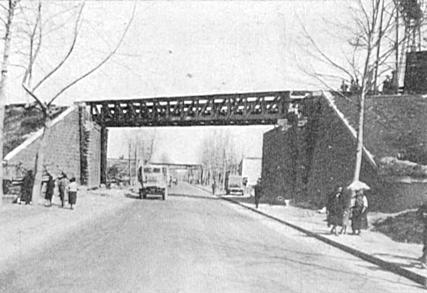
Figure 20. - Line 89. Bridge over main Naples-Capua road North of Aversa. The bridge, a 75' through U.C.R.B., was constructed by 150 Rly. Constr. Coy. R.E., under Job Nº. 89/5, from 15 March 1944 to 27 March 1944.
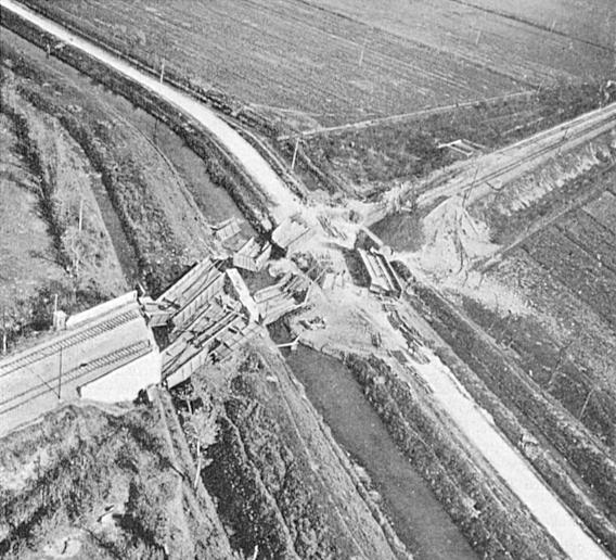
Figure 21. - Line 89. Bridge 11 at Km. 168.9 over canals and roadway showing extent of demolition. The repair, using 2 U.C.R.B. spans, 1 - 40' Sectional plate girder and 1 R.S.J. span, was carried out by 160 Rly. Constr. Coy, R.E., under Job Nº. 89/17, from 31 March 1944 to 30 April 1944.
of route, was processed by the "Rooter" over 13 kilometres of route, and over the remaining 50.5 kilometres of route the track was demolished by cutting the centre of each rail with explosive charges. Bomb damage was heavy at all main stations.
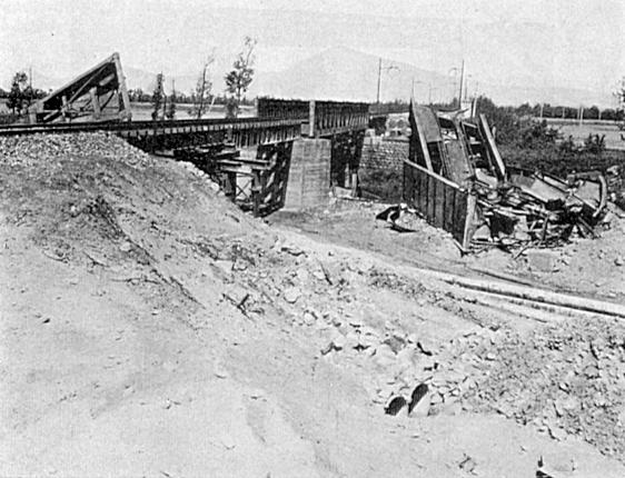
Figure 22. - Line 89. Bridge 11 showing the repair carried out. (See Figure 21).
The repair of the line was undertaken in four stages. First, the section from Naples to Aversa (19 kilometres) was repaired by M.R.S. American Section with the assistance of Engineer Troops, U.S. Army, as part of the Naples base development in October 1943. Second, the section from Aversa to the North end of the Massico tunnel (39 kilometres) was repaired by Nº. 1 Railway Construction and Maintenance Group R.E. with 150 and 160 Rly. Construction Coys. And 46 M.E. (Tn) Platoon R.E. under command (signal and telegraph work by 3 Rly Tele. Coy. R. Sigs.) as part of a plan to give rail support to 5 Army during March, April and May 1944. Third, the section from the North end of the Massico tunnel to Campoleone (112 kilometres) was repaired by M.R.S. American Section with the assistance of Engineer Troops, U.S. Army, and a detachment from 187 M.E. (Tn) Coy. R.E., as a continuation of the work commenced by Nº. 1 Rly. Construction and Maintenance Group R.E., during the period May, June, July 1944. Work on this section was discontinued at Campoleone because it was found quicker to open out to Rome over a branch line from this point, than over the main line. Fourth, the final link from Campoleone to Rome (34 kilometres), containing seven demolished high viaducts, was repaired by I.S.R. Contractors.
There are three reconstruction works on this line which merit special - Volturno Bridge - Massico Tunnel and Garigliano Bridge.
a) Volturno Bridge - Cancello Arnone.
The original bridge at this point consisted of a three span half through lattice girder bridge. A separate set of spans was provided for each of the two tracks. The size of the original spans was about 38 metres. All the steel spans had been demolished beyond hope of repair or salvage. Both piers were demolished down to about 25 ft. below rail level. The abutments alone were undamaged.
Reconstruction of the bridge was carried out by 150 Railway Construction Company, R.E. under the direction of Nº. 1 Railway Construction and Maintenance Group, R.E. Work commenced on 25 March 1944, the bridge was opened for traffic on 20 May and work finally completed on 25 June 1944.
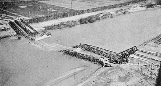
Figure 23. - Line 89 Bridge over River Volturno at Cancello Arnone, showing extent of demolitions.
There was considerable interest attached to this reconstruction from the very start. The river was deep and covered nearly the whole of the gap at all times. The length of the spans was ideally suited to the use of standard W.D. Lattice Girder spans. On the other hand, nobody in Italy had ever erected a Lattice Girder under active service conditions and only a few were acquainted with the material through the medium of Tn. Training Centre. Among the advantages were ease of access to the site and close proximity (20 miles) to Tn. Stores Depot. Although the work was carried out with the greatest energy in all its stages, the various factores combined to give a "Bridging School" atmosphere to the whole proceedings, and in fact much vital information was acquired by all concerned about the erection and launching of this type of bridge.
The bridge site is at the North end of Cancello Arnone Station yards, which allowed ample rail facilities for crane working, erection track and trolleying materials backwards and forwards to the bridge. Road access to the station and to both banks of the bridge site was adequate as long as weather was fine. In wet weather, access to the bridge site was only possible by rail to the South bank. During the whole period of construction, only two days of rain were experienced, a factor which contributed largely to the rapid progress made.
The works was divided into two distinct phases - one, the reconstruction of the piers and modification of the abutments, and two, the erection of the spans. As railhead had not reached Cancello Arnone when work commenced on the bridge, the first span was delivered to site by road and erected by means of the gantry shewn in Plate Nº. 19 (Supplement Nº. 3 N.O.M.R.E. Part 3). Once railhead reached Cancello Arnone, materials for the second and third spans were forwarded by rail, and a Brownhoist crane was used for assembly.
As regards the substructure, both abutments were sound but needed thickening 2 ft. 6 ins. to suit the spans, as it was not possible to alter the piers.
Both piers were demolished to 25 ft. below rail level and this level was equal to 1 ft. above lowest water level and 4 ft. below highest water level experienced during reconstruction. The piers were 8 ft. 6 ins. wide with 1 ft. 6 ins. steps at lowest water level. Parts of the cutwater were blown to 6 ft. below water level. Due to the span length, it was necessary to build up from these steps, giving a pier width of 12 ft. 2 ins. As the water level was above the level of the demolition at the time of commencement of reconstruction of the piers, preliminary courses were composed of bagged concrete. When water level was cleared the piers were brought up with masonry walls, with a core of concrete to dimensions 30 ft. x 12 ft. 2 ins. Average daily progress on each pier was 1 ft. 6 ins. with 4 Sapper Masons and 8 Italians. Dressed stone was collected from platform copings from all nearby stations and was mainly 12 ins. square to 18 ins. x 10 ins. in varying lengths. Materials were carried out to the piers on tubular steel scaffold runways built on the old steel wreckage.
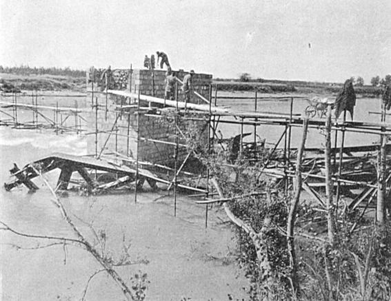
Figure 24. - Line 89. Bridge over River Volturno at Cancello Arnone. The repair, using Standard Lattice Truss Spans, was carried out by 150 Rly. Constr. Coy., R.E., under Job Nº. 89/12, from 25 March 1944 to 9 June 1944. In the figure above, masonry work is in progress on the demolished piers.
Erection of the steelwork was carried out on the South bank of the river, each of the three spans being erected successively in the same spot. No points of outstanding interest arose in this part of the work.
The spans were only partially rivetted before launching. Rivetting was completed after the bridge had been opened to traffic.
The pulling tackle used to launch the spans was placed on the far bank (a) because the same position would suit all three spans and (b) there was less likelihood of the tackle fouling the spans on the trolleys. The tackle itself consisted of two 3 ton winches pulling through two 2 inch S.W.R. 2/1 tackles which were in turn connected to the span by a double 3 inch S.W.R.
Launching Nº. 1 span took 7 hours, Nº. 2 span took 4 hours 40 minutes and Nº. 3 span 3 hours 25 minutes. These times include the time taken to dismantle the trolleys, which averaged one and a half hours - pilot trolley or rear trolley half and hour, and the compensating trolley one hour, and this time was taken on a pier - on a bank the work is much simpler and takes only three quarters of an hour for all trolleys.
Heavy standard trestling was used for lowering gantries. The average time taken over the lowering operation, including disconnection of tail frame and nose was 12 hours.
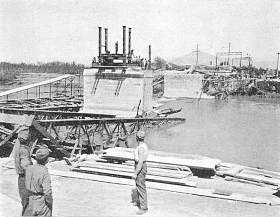
Figure 25. - Line 89. Job Nº. 89/12, River Volturno, showing the reconstructed piers, and the lowering and receiving gantry in process of erection. View looking North from South bank.
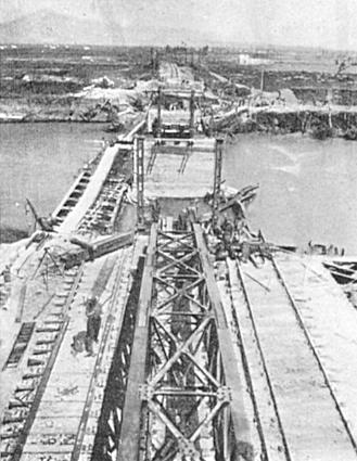
Figure 26. - Line 89. Volturno Bridge. General view showing launching nose and work in progress at 2 May 1944. The tubular steel scaffolding runaway constructed on top of the demolished original span can be seen on the left of the figure.
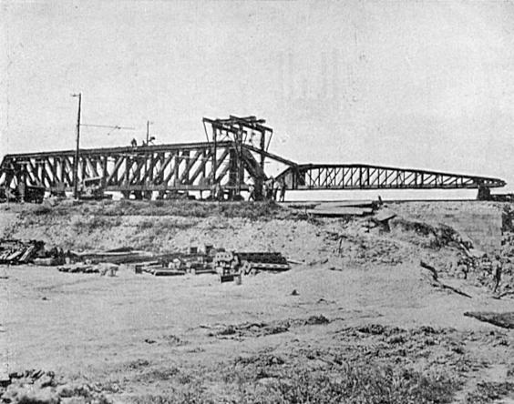
Figure 27. - Line 89. Volturno Bridge. First girder and launching nose assembled ready for launching 2 May 1944.
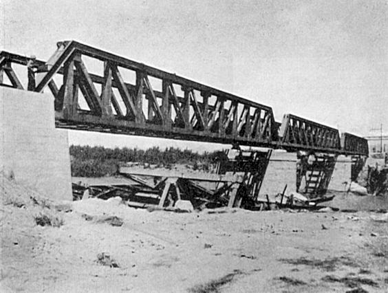
Figure 28. - Line 89. Volturno Bridge. Looking North from South Bank, the completed repair.
Removal of gantries and skidding the girders out took on the average about six hours.
The cross girders complete with knee braces were placed in one operation. It was found that a crane for this part of the work was invaluable (a) for lifting the travelling gantry on to the main girders and (b) for placing the end girders which are not easy to place without some suitable lifting tackle. When a crane was used, the flooring was placed in 14 hours; without the use of a crane the operation took 22 hours.
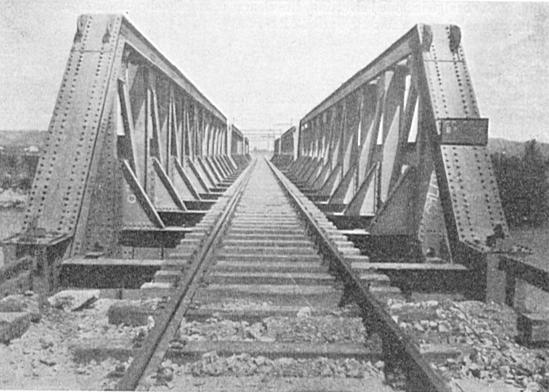
Figure 29. - Line 89. Volturno Bridge. Looking North over the finished structure.

Figure 30. - Line 89. Volturno Bridge. The new bridge from the upstream side.
It should be particularly noted in fairness to the unit concerned that the dates quoted at the beginning of this description for commencement and completion of work etc. in no way give a fair picture of the enterprise with which the job was carried out. Although reconstruction commenced 57 days before the bridge was opened to traffic, pressure of other works was so great that for 21 days it was only possible to allocate a skeleton force of less than 50 Sappers to the job for preliminary clearance works. Only during the final 36 days was it possible to build the task force from a section to the complete Company. The work carried out during the 36 days after the opening of the bridge included rivetting, site clearance and flood protection and was carried out by a task force of only a few men at odd intervals.
b) Massico Tunnel.
The Massico Tunnel lies 11 kilometres to the North of the Volturno Bridge just described and carries Line 89 under the mountain of that name. It is 5,378 metres long. For the greater part of its length in the central part of the tunnel, it is driven through sandstone. Near the portals, the stratum changes from sandstone through gravel to clay loam. The mountain rises evenly on a gradient of about 1 in 5 from each portal. The tunnel itself is of approximately circular section 9 metres in diameter and carries two tracks. The lining is approximately 1.3 metres thick and is constructed of brickwork and stone masonry.
The tunnel was demolished at 17 points, all except one of the demolitions being within 1,000 metres from the North portal. The demolitions were made in the sides of the tunnel and in all except four cases the crown of the lining was still standing. This was probably due to the hardness of the strata through which the tunnel id driven. For the same reason, only in two of the demolitions, the two adjacent to the North portal, was the tunnel bore completely blocked. The lengths of the demolitions varied from 2 to 18 metres.
Clearance of the tunnel and its reopening to traffic was effected by 160 Railway Construction company, R.E. and 46 M.E. (Tn) Platoon, R.E. under command of Nº. 1 Railway Construction and Maintenance Group, R.E. Restoration of the lining was carried out under traffic by I.S.R. Contractors working directly under M.R.S. supervision. Work was commenced on 28 March 1944, the tunnel was opened for traffic on 25 May, and the contractor's work of restoring the lining continued to the end of the year.
Owing to the fact that the two demolitions at the North portal completely blocked the tunnel, whereas all the other demolitions only effected a partial blockage, it was possible from the beginning to work on several of the internal breaks at one time, but access for men and materials was from the South portal through four kilometres of tunnel. Clearance of these 15 internal demolitions gave no trouble, but as it had been decided to abandon the work of relining to a contractor, it was necessary at six of the more serious demolitions to provide some safeguard against falls of earth while the tunnel was in use and before the lining could be restored.
This safeguard was provided by the erection inside the tunnel of a light steel trestle framework. This framework was positioned centrally in the tunnel and was roofed with precast reinforced concrete slabs found locally and the sides were covered with 2 inch boarding. This was only designed to guard against light falls of small quantities of earth or small boulders as inspection of the cavities indicated that any more serious falls would be unlikely. In this it was successful and at no time after opening of the tunnel was it ever closed due to earth falls.
The two breaks adjacent to the North portal gave more trouble. Owing the fact that the overburden at this point was of no great depth (about 7.5 metres) it was decided to clear the break next to the portal by excavation from the surface of the ground above. This was done with draglines, and scrapers were operated to clear the spoil form the draglines. This work went smoothly and was completed without incident. The sides of the excavations were dressed back to the angle of repose, to obviate any possibility of slips later. The excavation was left open and the line was not protected with the trestle framework.
The second break from the North portal was the most difficult of all to clear, and as perforce it had to be tackled last of all, it was the keypoint to the opening of the line. The depth of overburden at this point (about 25 metres) was too great to justify excavation down from ground surface. No access to the North side of this break was possible until clearance of the break adjacent to the portal was nearly complete. Access to the South side of the break was through 5 kilometres of tunnel and past 15 other breaks and was therefore extremely difficult. In actual fact, little could be done to clear this break until access could be obtained to it, from the North portal.
When work became possible on this break, it was found that not only did it completely block the tunnel, but that in addition, it gave indications of proving to be treacherous. In fact several
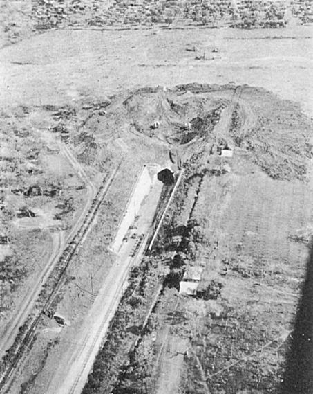
Figure 31 - Line 89. Massico Tunnel, North Portal. General view showing excavation works in progress to clear the demolition. Work was carried out by 46 Mech. Equip. (Tn.) Platoon, R.E., under Job Nº. 89/13, from 24 March 1944 to 6 June 1944.
falls from high up in the demolition took place when the clearance of the debris was started. Clearance of the debris was started by use of a 10 R.B. excavator fitted with a face shovel. When the earth started to fall, this machine was withdrawn and a 19 R.B. dragline substituted. This was used with its boom very low and cleared debris by scraping towards itself. The debris was then loaded to dumpers for disposal. As the length of break in the tunnel lining at this point was only 40 ft. it was possible to clear most of the debris in this way. When sufficient space had been cleared, a trestle shield was erected and the remainder of the debris cleared by hand. In this way it was possible to obviate to a very great extent, the necessity for men working in dangerous places at this spot.
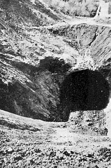
Figure 32. - Line 89. Massico tunnel, North Portal. Looking North and down into the crater which was blown clean through from the tunnel to ground surface.
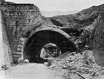
Figure 33. - Line 89. Massico Tunnel, showing the damaged North Portal. The repair to reopen the tunnel was carried out by 160 Rly. Constr. Coy., R.E., under Job Nº. 89/13, from 24 March 1944 to 6 June 1944. The crater referred to in fig. 32 can be seen in the background.
c) Garigliano Bridge - Minturno.
The bridge over the River Garigliano just South of Minturno consisted of a single steel span of length 72 metres. The height of rail level above the river bed level was about 15 metres and the height of rail level above mean water level about 7 metres. The steel superstructure was destroyed by the demolition beyond hope of recovery or salvage and was lying in the river bed about 15 metres downstream from the line of the original bridge. Abutments were demolished down to mean water level, but the foundations were good.
Reconstruction of the bridge was carried out by 713, 715, 719 and 727 Railway Operating Battalions U.S.A. under command of 703 Railway Grand Division U.S.A. The bulk of the work was done by 719 and 727 Rly. Operating Battalions. Work commenced on 6 May 1944 and traffic was passed over the new bridge on 5 June and the work was completed on 10 June.
It was decide to repair the bridge as a single span, using Roth Waagner bridging material captured near Naples. The bridge was, of course, only reconstructed for single track, although the original span had carried double track.
Considerable forethought had been given to the reconstruction of the bridge and as a result work proceeded rapidly and without hitch. The abutments were reconstructed in concrete on the old foundations. The first stage in the erection of the steelwork was the construction on the South bank of a counterweight of Roth Waagner material. Erection of the bridge was then carried forward from this point and the span cantilevered out across the gap. When the limit of equilibrium was reached, the suspended end of the bridge was caught on a Vee Trestle pier previously placed in the water-way by flotation from pontoons. Fabrications of the span was then continued as a propped cantilever. The suspended end was caught on a second Vee trestle pier before reaching the North bank. Erection of the bridge was carried out by use of a crawler travelling along the top boom of the span, as is standard Roth Waagner practice. The counterweight and Vee trestle piers were dismantled on completion of erection of the main span.
This bridge represents the longest single span railway bridge erected by Allied forces in Italy during the whole campaign.
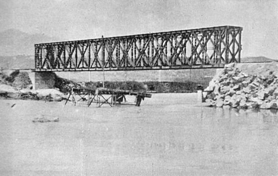
Figure 34. - Line 89. The Garigliano Bridge South of Minturno. The repair was carried out by 713, 715, 719, 727 Rly, Optg, Bns., U.S.A. under Job Nº. 89/40, from 6 May 1944 to 5 June 1944. This bridge is the longest single span railway bridge erected by the Allies in Italy. It is a 72 metres Roth Waagner structure of captured enemy materials.
| Prev | Contents | Next |
[Railway reconstruction Italy 1943-1946 published by Royal Engineers, 1946]