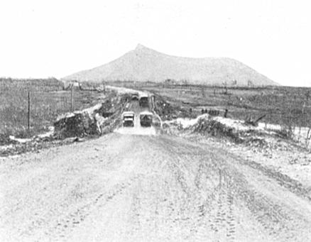
Figure 35. - Line 90. The railway track between Mignano and Cassino was removed and the formation used as a highway known as "Speedy Highway".
[Railway reconstruction Italy 1943-1946 published by Royal Engineers, 1946]
| Prev | Contents | Next |
Chapter II
DESCRIPTIVE ACCOUNT OF RAILWAY CONSTRUCTION ACTIVITIES
Section III.
Railway Construction considered in relation to the ultimate Railway system
4. - Line 90 - Rome-Cassino-Naples.
This is the old original line between Rome and Naples, and until the construction of Line 89 was the main link between the two cities. It was double track throughout and was steam operated.
Leaving Naples in a North easterly direction, the line cuts across the plain to the North of the City. It then turns North west and runs along the foothills at the North east edge of the plain. Cutting across a spur in these hills, the line drops down into the valley of the River Liri near the fortress town of Cassino. Passing through Cassino, the line follows the Liri, and then its tributary the Sacco up to the watershed at Palestrina on the Eastern flank of the Alban hills. The line the runs around the shoulder of the Alban hills and drops down into Rome.
The scale of demolitions on this line was very variable. For many kilometres on either side of the hotly contested town of Cassino, destruction was more complete than on any other railway in Italy. In addition, part of the line in this section was further damaged by the Armies converting it into a highway for their own uses. Further North, the destruction decreased in intensity and the last 45 kilometres into Rome were virtually undamaged. 53 bridges out of a total of 79 bridges, of span of 5 metres or greater, were demolished. 2 tunnels out of a total of 4 tunnels were damaged, but fortunately not severely. Out of the 249 kilometres length of this line, the track was destroyed by deliberate demolitions over 131 kilometres of route. Of the 131 kilometres demolished, the track had been processed by the "Rooter" over a length of 36 kilometres. Of this length of 36 kilometres, 20 kilometres had subsequently been cleared by 5 Army and converted into a highway with consequent loss of all the remnants of track. Over the remaining 95 kilometres, the track was demolished by cutting of the rails with explosive charges.
Figure 35. - Line 90. The railway track between Mignano and Cassino was removed and the formation used as a highway known as "Speedy Highway".
The repair of the line was undertaken in three stages. First the section Naples to Cancello (22 kilometres) was repaired by 161 Railway Construction Company, R.E., under the command of Nº. 1 Railway Construction and Maintenance Group, R.E. during October 1943, as part of the Naples Base Development scheme. Second the section Cancello to Mignano (72 kilometres) was repaired by the American Section of M.R.S. during the period October, 1943 to February 1944 to give rail support to 5 Army. The final section Mignano to Rome (155 kilometres) was repaired by Nº. 1 Railway Construction and Maintenance Group, R.E. with 150, 159, 160 and 161 Railway Construction Companies, 1 Railway Bridging Section, 46 M.E. (Tn) Platoon, R.E. and 190 Railway Operating Company, R.E. under command, and by 1212 Railway Construction and Maintenance Group, R.E. with 10 Railway Construction Company, 2 Railway Bridging Section and 45 M.E. (Tn) Platoon under command during the period April to July, 1944.
The first train ran into Rome on 2 July, 1944, and by virtue of being the first rail connection made by the Allies with the capital, received some publicity in the press.
Some of the repairs to the line carried out at high speed in the rapid advance during the Summer of 1944 began to give trouble when winter floods started and 39 and 40 Railway Construction Companies, S.A.E.C., under command of R.C.E. S.A.E.C., and the construction companies of 715 and 719 Railway Operating Battalions, U.S.A., under command of 704 Railway Grand Division, U.S.A., were brought back to carry out work on the reinforcement of repairs and additional flood protection works during the Autumn of 1944.
Although the repair of this line involved a considerable amount of work and attracted considerable attention both from its strategic and political importance, none of the individual works on the line were in any way remarkable as judged by the standards of the campaign as a whole. It is therefore difficult to select any particular jobs as meriting special description. Among the more interesting of the work on the line, however, were the Volturno Bridge, the Peccia Viaduct and the Liri Bridge.
a) Volturno Bridge at Capua.
This bridge originally consisted of seven steel plate girder spans each of 23 metres span carrying double track. The whole of the steelwork was demolished beyond hope of recovery and the abutments and three of the piers were demolished.
Reconstruction of the bridge was carried out by the construction companies of 713 and 727 Railway Operating Battalions, U.S.A., under the direction of 703 Railway Grand Division, U.S.A., work commenced on 28 October, and was completed on 23 November, 1943.
Supplies of bridging at this time were very short and such supplies as were available were of British origin and were being used up by British units as soon as they were discharged from the ship. Local production, on which the Americans depended for much of their future bridge spans, was not yet showing any results. The only other source of supply was a stock of Roth Waagner bridging found at an Italian bridging school near Naples. Although wasteful, there was virtually no alternative to the use of the Roth Waagner material on this occasion.
The remaining stump of one of the demolished midstream piers was capped with a concrete slab and a Light Steel Trestle pier, 5 bays by 2 bays by 21 ft. high, erected thereon. The original pier at the North end of the bridge was only slightly damaged and was built up to the requisite height by timber cribbing. The second pier from the South end was intact and was re-used. The second pier from the North end, although undamaged was not used in the reconstruction. The abutments had been of very small height and timber cribs about 10 ft. in height were erected at these points to carry the weight of the new girders.
Three through spans each 46 metres in length with an approach span of 25 metres length at the North end were used. Each of the large spans spanned two of the spans of the original bridge. As was standard practice, the new bridge was constructed for single track.
b) Peccia Viaduct at Mignano.
The original bridge at this point had consisted of five masonry arches of 15.60 metres clear span and of a height of 27 metres from bed of stream to rail level. This incidentally was typical of a number of bridges along this section of line, all of which were demolished. The bridge lay in a section of the line which had been in use as a highway (referred to above) and in order to pass road traffic, the banks and debris of the demolished bridge had been bulldozed away and a Bailey Bridge thrown across the bottom of the gap.
The reconstruction of the bridge was carried out by Nº. 1 Railway Bridging Section, R.E. reinforced by a detachment from 161 Railway Construction Company, R.E. all under command of Nº. 1 Railway Construction and Maintenance Group, R.E. Work commenced on 24 April 1944, the bridge was opened for traffic on 2 June and all work was completed by 10 June.
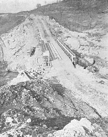
Figure 36. - Line 90. The Peccia viaduct approximately 1 mile North of Mignano, showing the complete obliteration of this 5 span viaduct. A Bailey Road Bridge was erected at a low level to take "Speedy Highway" over the Peccia stream.
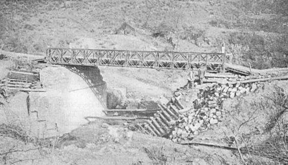
Figure 37. - Line 90. The Peccia Viaduct. Another view of the low level Bailey crossing the Peccia before railway repairs were started.
Design and preparations for the repair of this bridge had been made by the American section of M.R.S. before the line was taken over as a British commitment. The American design envisaged a partial restitution of the embankment at each end of the gap, and the remainder of the gap to be spanned by steel plate overhead crane girders, salvaged from a steelworks in Naples, supported on steel piers. As this scheme appeared to be as good as any other and as all the necessary material had been brought to site in readiness, it was adopted.
The repair was carried out as follows. The original two central pier bases were used as footings for 3 by 2 bay L.S.T. piers, 56 ft. O ins. high. The two piers on either side of these piers were pre-fabricated steel trestles whilst the two abutments were 3 by 1 bay trestles, 31 ft. and 26 ft. high respectively, spoil being filled through these trestles to their angles of repose, thus making them more or less bank seats. With the exception of the two central piers where the footings were on the original pier foundation, complete new concrete footings and concrete foundations reinforced with rails were poured.
The foundations and trestling for the South abutment and piers 6, 5, and 4 were carried out first. The abutment trestling was guyed back to anchors fastened into the existing consolidated embankment, tension being obtained in the guys by the interposition of railway wagon couplings. Filling behind the abutment trestle pier was then carried out. Since all the trestle piers were a considerable height, the bottom grillages were concreted over the ensure fixity of the base. Whilst construction proceeded with the trestle pier founds, and the filling in behind the abutment trestles, the spans were brought up to the site on standard launching trolleys in the following order - Spans 5, 6, 7, 3, 4, ,1, 2. Since these steel spans were originally crane girders, there was a rail welded along the full length of what is now the bottom flange of each girder. For this reason it was impracticable to use the standard Tn. type of roller, it was therefore decided to use the rocker type Bailey Bridge launching roller which is approximately 9 ins wide.
Due to the restriction in space for lowering the girders it was further decided to use a gantry on piers 3 and 4 to act as a lowering and steadying device, each gantry having four 12 ton Felco Blocks. Jacking space was much restricted, hence, when it was necessary, a temporary jacking beam of steel or timber was fitted between the girders for use when the head-room was too small to permit the head of the jack to be directly under the girder.
The scheme of launching the bridge was as follows. Span 7 is at Mignano or South end and span 1 at the Cassino or North end, intermediate spans are numbered consecutively. Spans 7, 6, 5 were coupled up as continuous girder and launched over the 7th, 6th, and 5th gaps thereafter being lowered by jacking and the gantry. Using this continuous girder method, it eliminated the necessity of a launching nose. The launching was by no means easy, however, as the line is on a 1.34 % grade down from Pier 7 to Pier 1. Working on such a steep grade as this, during lowering operations, to prevent accidents due to slipping, the spans were lowered horizontally, fleeting the packs about 1 inch at a time on the safety cribs.
The launching and safety cribs built on top of the piers were of 12 by 12 timbers securely wired down to the piers by SWR. This precaution proved to be wise, as there was a considerable thrust on the piers when the front of the first span reached the rollers. Further, the rail fixed to the underside of the girders tended to catch the second roller of the launching roller rocker and to jam, any attempt to pull after jamming occurred would only have overturned the trestle piers, or, at least, the timber cribs. Accordingly, just as the girder was about to jam itself in the roller it was given a slight lift on a jack just sufficient to let it roll forward on to the second roller. Here again, evidence was seen of the action of the steep incline. Having got the girders over the appropriate gap, they were fastened at one end to the gantry and, jacking from three points (i.e.), for the first three joined spans, on the head of 50-ton quick release jacks, the girders were lowered a small increment at a time as described above. Great care was taken in the synchronising of the lowering as there is considerable whip in a 3 by 47 ft. 2½ ins. length. Having lowered spans 7, 6 and 5, aligned, levelled and separated them, track was laid over, preparatory to the launching of the remaining spans. All the rivetting required to each of the above spans was carried out prior to launching.
The next set of spans to be launched were 4 and 3. For this launch, since 4 was 61 ft. 9½ ins and 3 was 47 ft. 2½ ins, 1 was connected to 4, which was connected to 3, and launching carried out as for the first set. After 4 and 3 were over the appropriate gaps, 1 was removed and 4 and 3 lowered using a system of jacking and safety cribs similar to that described in the first launch. Similar precautions were adopted when lowering, and once again, after separating and aligning the spans, track was laid over them for the launch of the final two girders, Nos. 2 and 1.
Spans 2 and 1 are equal hence span 2 was loaded with rail to act as counterbalance; this time the winches were fastened to the bridge to give a more direct pull. All other arrangements were as for the previous spans.
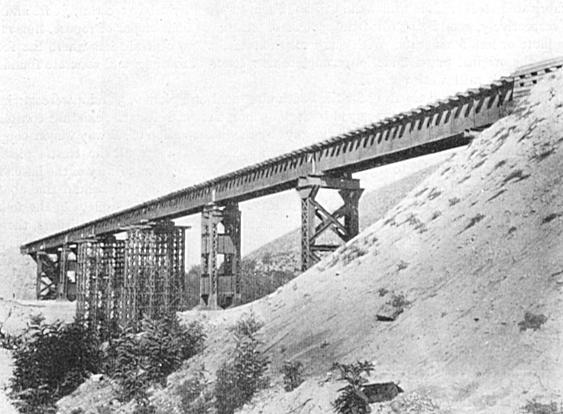
Figure 38. - Line 90. The Peccia Viaduct as reconstructed by Nº. 1 Railway Bridging Section, R.E., under Job Nº. 90/46, from 24 April, 1944 to 10 June, 1944. 46 Mech. Equip. (Tn) Platoon, R.E. carried out the earthworks. Crane girders from a steel works in Naples were used to span the gap.
c) Bridge over River Liri at Isoletta.
The original bridge at this point consisted of a single girder about 140 feet in length carried on masonry abutments. The height of rail level above mean water level in the river was about 60 feet. The retreating enemy had demolished the steelwork which was found lying in a tangled mass in the river bed. Each abutment had also been very thoroughly demolished and was deeply buried in debris and spoil from the bank behind.
Reconstruction of the bridge was carried out by 161 Railway Construction Company, R.E. Work commenced on 9 June, traffic was passed over the bridge on 2 July and work was completed on 21 July, 1944.
Owing to the great height of the bridge, and the fact that the gap was a wet one, it was immediately apparent that the only satisfactory solution was to use a standard Lattice Girder span founded on a reconstruction of the original abutments. In the early stages of the reconstruction some difficulty was experienced in locating the stumps of the demolished abutments, owing to the large quantity of rubble and earth piled on top of them. They were however located and were reconstructed in concrete, heavily reinforced with rails, for a height of about 20 feet. Owing to the length of time taken to locate the foundations, time did not permit the complete reconstruction of the abutments in concrete, and they were therefore brought up to the remaining height with Heavy Steel Trestle piers about 20 ft. in height.
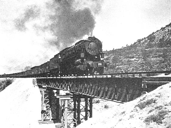
Figure 39. - Line 90. Bridge at Km. 151.56 just South of Rocca D'Evandro, reconstructed by 161 Railway Construction Company, R.E. under Job Nº. 90/37, from 18 April, 1944 to 10 June 1944. The repair as for the Peccia Viaduct incorporated Crane Girders ex Naples.
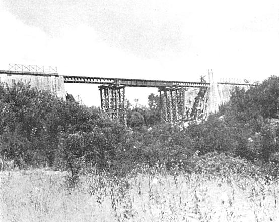
Figure 40. - Line 90. Bridge at Km. 117.31, North of Roccasecca. The reconstruction was carried out by 160 Railway Construction Company, R.E. under Job Nº. 90/60, from 1 June, 1944 to 24 June, 1944. The repair involved 2 R.S.J. spans and 1 Nº. 40 ft. Sectional Plate girder.
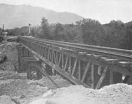
Figure 41. - Line 90. Bridge at Km. 75.92 between Ferentino and Morolo. Reconstruction was carried out by 10 Railway Construction Company, R.E. under Job Nº. 90/69 from 8 June, 1944 to 30 June, 1944. The repair involved 3 Deck type U.C.R.Bs.
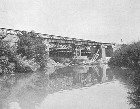
Figure 42. - Line 90. Bridge at Km. 65.867 between Sgurgola and Anagni. Reconstruction was carried out by 10 Railway Construction Company, R.E. from 8 June, 1944 to 28 June, 1944 under job Nº. 90/70. The repair involved 2 N.º 40 ft. Sectional Plate girders and 2 Nº. 27 ft. R.S.J. spans.
The use of trestling to complete the abutments necessitated dressing back the bank behind the abutments. This further necessitated the use of an approach span at each end of the bridge, and a 35 ft. standard R.S.J. span founded on a sleeper crib bankseat was therefore used at each end of the bridge. A 143 ft. 6 ins. Lattice Girder span was used for the central span.
By dint of much hard effort and all night working, the unit managed to pass traffic over the bridge 5 days ahead of schedule, and removed the last barrier to rail traffic on the road to Rome.
d) Other works of interest on this Line are shown in figures, 39, 40, 41 & 42.
| Prev | Contents | Next |
[Railway reconstruction Italy 1943-1946 published by Royal Engineers, 1946]